
RFQ Checklist
Accelerate your mold quotation process and eliminate costly engineering revisions. Use our comprehensive RFQ checklist to ensure your CAD files, 2D prints, press platen specifications, resin grades, and hot runner requirements are fully defined for accurate 48-hour fixed tooling quotes.
Quick Summary: Five Core Pillars of a Complete Tooling RFQ
A complete injection mold RFQ requires five technical deliverables: (1) native 3D CAD files (.step or .x_t) and 2D prints with GD&T; (2) target tooling class (SPE Class 101 to 103) and annual part volume; (3) exact resin supplier, grade, and shrinkage value; (4) target injection press platen dimensions, tie bar clearances, and locating ring diameter; and (5) hot runner preferences, including valve gating and preferred manifold suppliers.
3D CAD Models & 2D Engineering Drawings
Incomplete or preliminary CAD geometry leads to quote discrepancies and delayed tooling kickoffs. For accurate steel sizing, parting line development, and slide actuation modeling, provide final geometry packages:
- 3D Solid Models: Provide native CAD (SolidWorks, Creo, NX) or neutral Parasolid (.x_t) and STEP AP214 / AP242 files. Avoid polygon meshes (STL / OBJ) which cannot be parsed for CNC toolpaths.
- 2D Dimensional Prints: Detail critical-to-function dimensions, Geometric Dimensioning and Tolerancing (GD&T) feature control frames, datum origins, and hole concentricity limits.
- Cosmetic Surface Callouts: Clearly identify appearance A-surfaces, SPI gloss grades (e.g. SPI A2 diamond polish), or specific texture numbers (e.g. Mold-Tech MT-11010).
- Permissible Ejector & Gate Zones: Highlight acceptable and non-permissible locations for ejector pin witness marks and gate vestiges.

Production Volume & SPE Mold Classification
Tooling capital expenditures must match commercial program lifecycle projections. The Society of Plastics Engineers (SPE) classifies injection molds into distinct categories based on shot volume and durability requirements:
| SPE Class | Target Cycles | Core / Cavity Steel | Mold Base Standard | Application Focus |
|---|---|---|---|---|
| Class 101 | 1,000,000+ | Through-hardened (H13, S136) 48-54 HRC | Hardened steel base min 280 BHN | High-speed packaging, medical, 24/7 automotive |
| Class 102 | Up to 1,000,000 | Pre-hardened or hardened (40-48 HRC) | Pre-hardened steel plate construction | Medium-to-high volume industrial & appliances |
| Class 103 | Up to 500,000 | P20 pre-hardened (28-32 HRC) | Standard #1 or #2 mold base steel | General commercial products & consumer goods |
| Class 104 | Up to 100,000 | Mild steel or aluminum | Standard low-carbon mold base | Low-volume bridge tooling and pilot launches |
Resin Data Sheet & Volumetric Shrinkage
Different polymers contract at drastically different rates during in-mold cooling. A mold built for Polycarbonate (0.5% to 0.7% shrinkage) will produce out-of-spec parts if run with Polypropylene (1.2% to 2.0% shrinkage).
- Exact Resin Brand & Grade: Specify polymer manufacturer and grade name (e.g. Sabic Cycoloy C6600 PC/ABS rather than generic “PC/ABS”).
- Filler & Reinforcement Content: Detail glass fiber, mineral filler, or carbon fiber percentages. Glass fiber increases steel abrasion and causes anisotropic shrinkage along orientation directions.
- Regrind Percentage: State maximum allowable regrind ratio (e.g. 0% for medical, up to 20% for industrial housings).
Press Platen Interface & Machine Specifications
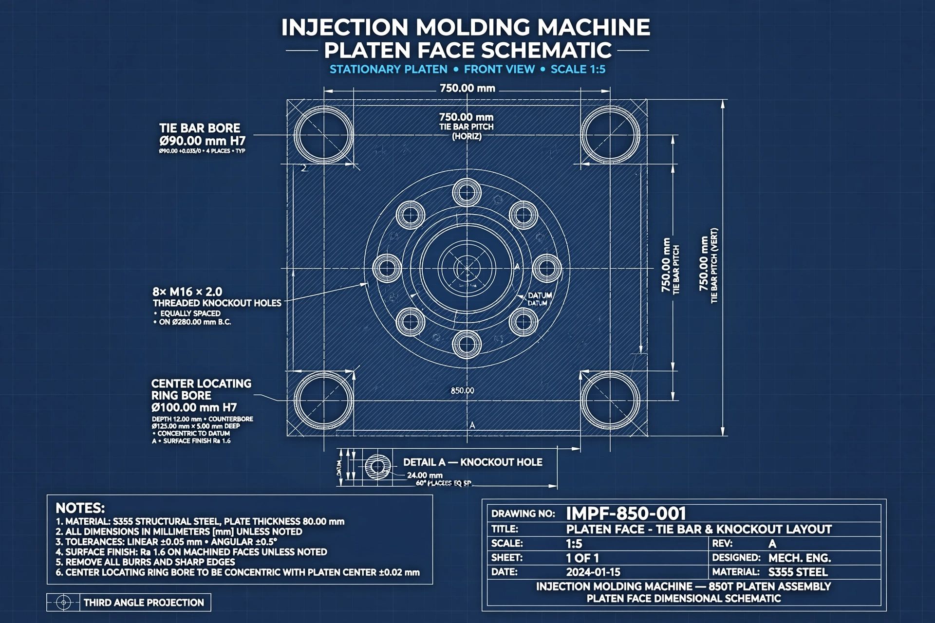
To ensure your export mold drops directly into your production press without platen modifications, include your press data sheet with the RFQ packet:
- Tie Bar Clearances: Horizontal and vertical clearance between tie bars to verify mold width clearance during tool installation.
- Locating Ring & Sprue Bushing Radius: Stationary platen register ring diameter (typically 3.990 inches for U.S. or 100/125/160 mm for metric presses) and spherical sprue nozzle radius (0.500 inch or R15.5 mm).
- Ejector Knockout Pattern: SPI center knockout pattern or multi-pin layout, including rod diameter and thread size.
- Maximum / Minimum Shut Height: Verify mold stack height fits within machine daylight parameters.
Hot Runner Manifold & Gating Architecture
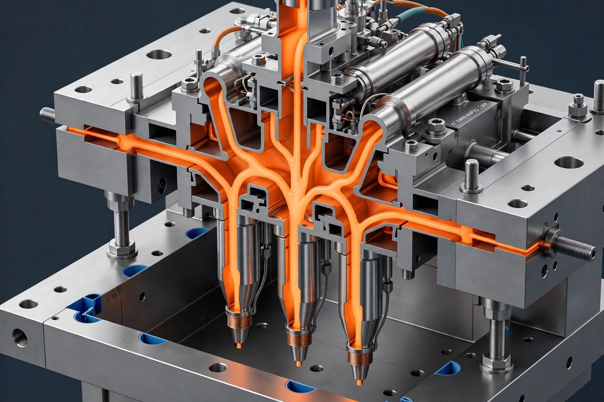
State your preferred melt delivery architecture to eliminate scrap runner regrinding and maintain rapid cycle times:
- System Style: Cold runner, cold runner with hot sprue bushing, hot tip thermal gate, or servo/hydraulic valve gating.
- Specified Manifold Supplier: Specify preferred hot runner manufacturers compatible with your facility spares inventory (e.g. Mold-Masters, Synventive, Husky, Yudo, HRS Flow).
- Temperature Controller Connectors: Indicate wiring standard (e.g. 24-zone DME standard 25-pin or 16-pin Harting connectors).
Tooling RFQ Readiness Audit
Select each technical specification item you currently have ready for submission to calculate your RFQ completeness score:
Frequently Asked Questions: RFQ Checklist
Submit Your RFQ Data Package for Rapid Review
Send your 3D CAD files, 2D prints, and machine specifications directly to Brandon Henderson in North Carolina. We conduct a preliminary DFM review and return an all-inclusive tooling quotation within 48 hours.