
Core Injection Molding DFM Principles
Every injection molded plastic part is governed by the physics of polymer crystallization and heat transfer. Cutting steel without conducting a comprehensive DFM review leads to visual sink marks, brittle weld lines, difficult part ejection, and prolonged cycle times.
Primary Geometry Checks
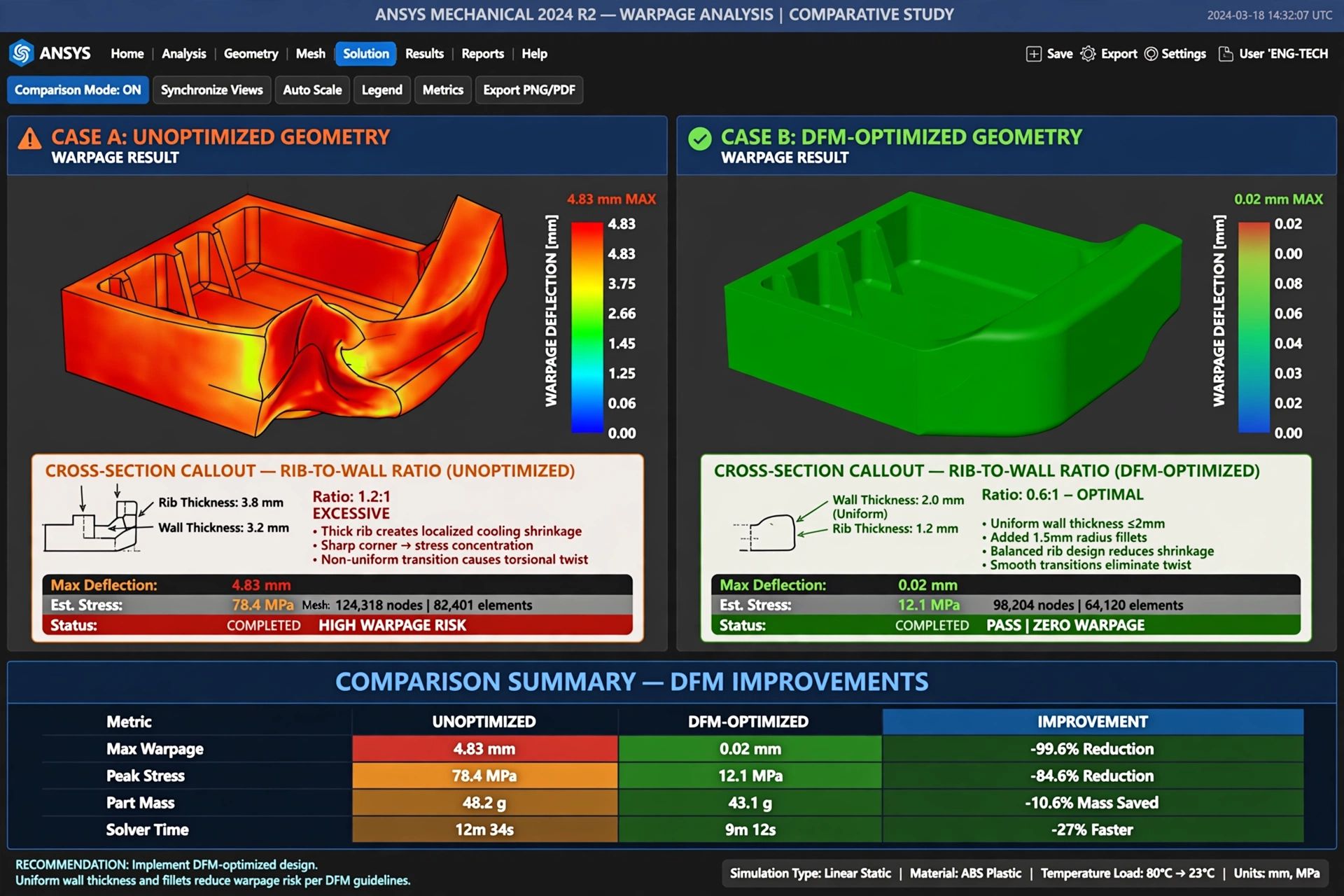
- Uniform Nominal Wall Thickness: Maintaining consistent wall thickness throughout the part prevents differential volumetric contraction that drives bowing and residual molded-in stress.
- Adequate Draft Angles: A minimum of 1.0 to 1.5 degrees draft per side on smooth surfaces, and 1.5 degrees per 0.001 inch of grain depth for textured cavities, ensures drag-free ejection.
- Rib-to-Wall Proportions: Structural ribs must not exceed 40 to 60 percent of the adjacent nominal wall thickness to avoid unsightly sink marks on cosmetic class-A outer surfaces.
- Internal Radii and Fillets: Sharp internal corners create sharp stress concentrations. A minimum radius equal to 25 to 50 percent of wall thickness distributes injection loads.
As noted in technical literature from the National Institute of Standards and Technology on polymer measurement science, mechanical anisotropy introduced during cavity filling cannot be reversed through packing pressure alone. Early geometric correction remains the most effective lever for achieving repeatable dimensional tolerances.
Moldflow Finite Element Simulation Capabilities
Key Moldflow Deliverables
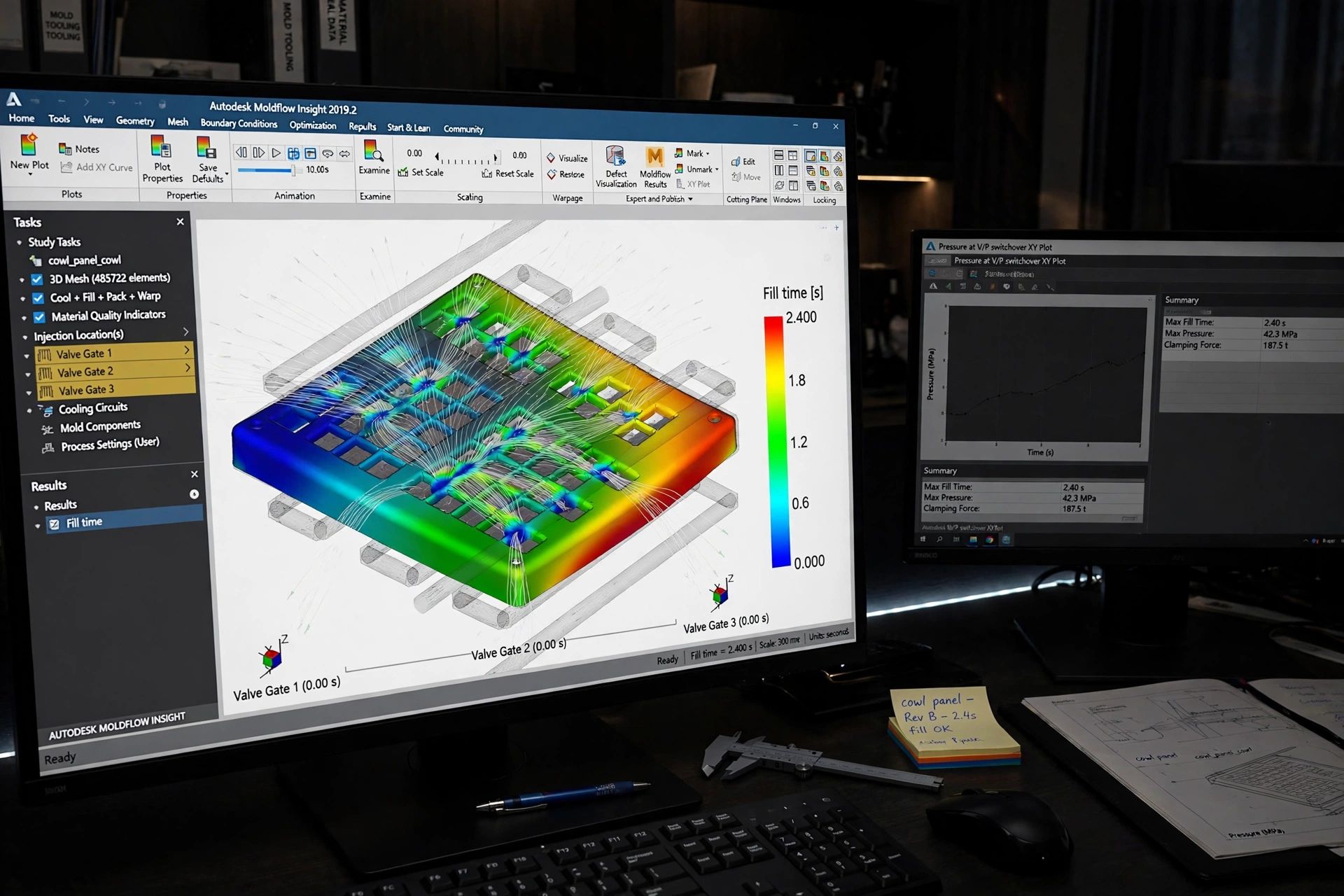
Our certified engineering team executes deep computational runs using Autodesk Moldflow Insight:
- Fill and Pack Analysis: Evaluates pressure drops, clamp tonnage requirements, and identifies hesitations in thin rib walls.
- Weld Line Prediction: Pinpoints where opposing melt fronts rejoin, allowing engineers to reposition gates so weld lines occur in non-critical cosmetic areas.
- Air Trap Mapping: Highlights trapped pockets of gas, specifying micro-venting slots (0.0008 to 0.0015 inch) along the steel parting line to prevent diesel burn marks.
- Fiber Orientation: For glass-filled polymers (like PA66-GF30), tracks fiber alignment to anticipate directional shrinkage and tensile strength changes.
Warpage and Volumetric Shrinkage Analysis
Plastic components shrink as they cool from melt temperature down to ambient room conditions. If shrinkage occurs non-uniformly across the component, residual internal forces induce twisting and out-of-flatness.
| Resin Type | Volumetric Shrinkage Rate | Warpage Susceptibility | DFM Mitigation Tactic |
|---|---|---|---|
| Amorphous (ABS, PC, PMMA) | 0.4% – 0.7% (Low & Uniform) | Low | Generous corner radii; balanced packing pressure |
| Semicrystalline (PP, PE, POM) | 1.2% – 2.5% (High Contraction) | High | Uniform wall thickness; conformal cooling circuits |
| Glass-Filled (PA66-GF30, PBT-GF) | 0.2% Parallel / 0.8% Perpendicular | Very High (Anisotropic) | Strategic gate positioning along structural load axes |
| High-Temp Engineering (PEEK, PPS) | 1.0% – 1.5% (High Crystallinity) | Moderate to High | Oil-heated mold temperature regulation (160°C+) |
For projects requiring advanced thermal extraction, explore our conformal cooling technology or examine our turnkey custom injection mold tooling capabilities.
Gate Location Optimization and Cold vs Hot Runners
Gating Best Practices
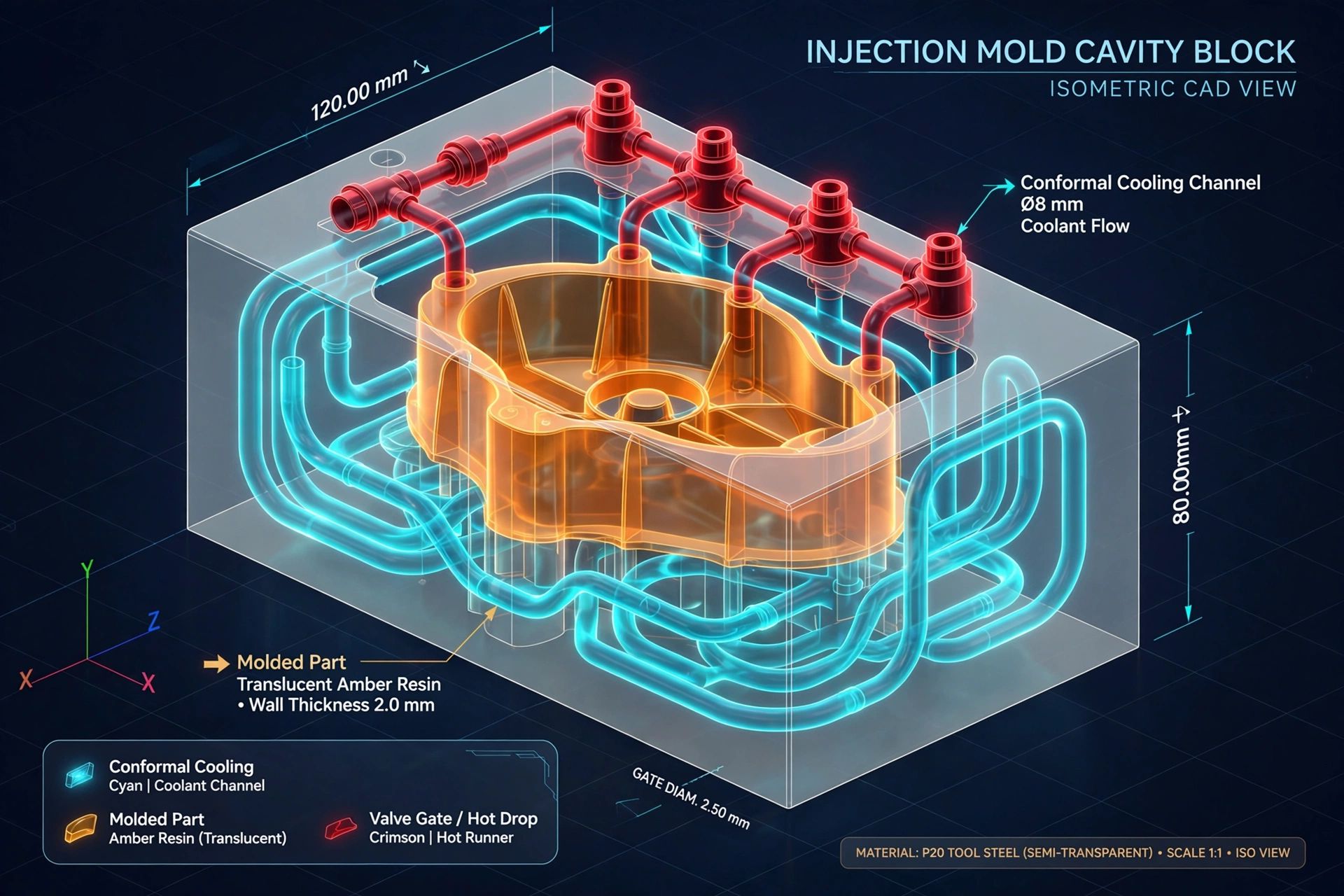
Positioning the gate into the thickest section allows packing pressure to feed molten resin continuously as thinner sections freeze off. Submarine tunnel gates and edge gates are suited for cold runner family molds, while valve-gated hot runner manifolds deliver cosmetic pin points with zero sprue regrind. Learn more on our export molds for U.S. presses page.
Interactive DFM Guideline Checker
Select your material family and nominal wall thickness to generate recommended draft angles, rib thickness ratios, and corner radii specifications.
Technical Sourcing FAQ: DFM & Moldflow
Get a Comprehensive DFM Review on Your Part CAD
Submit your 3D CAD models to Brandon Henderson in North Carolina. Our engineering department will identify potential molding traps, optimize wall thickness transitions, and propose tooling layouts.