
Thermal Physics and Turbulent Coolant Flow
In high-volume injection molding, over seventy-five percent of the total cycle time is dedicated to plastic solidification. Traditional straight gun-drilled water lines cannot access deep core pins, sharp corners, or round screw thread profiles, leaving pockets of heat that dictate extended cooling delays.
Maintaining Turbulent Flow (Re > 4,000)
Laminar cooling water flow forms an insulating stagnant boundary layer along channel walls that drastically impedes heat transfer. Conformal channels are engineered with optimized hydraulic diameters, internal ribs, and spiral baffles to maintain Reynolds numbers exceeding 4,000.
This high-velocity turbulence extracts heat from molten resin up to four times faster than straight drilled lines, preventing hot spot crystallization defects. For full tool layouts, explore our custom injection mold tooling capabilities.

Conformal vs Conventional Drilled Cooling
| Thermal Characteristic | Conventional Gun-Drilled Tooling | 3D Laser Sintered Conformal Cooling | Impact on Production |
|---|---|---|---|
| Cooling Channel Path | Straight intersecting blind holes | Continuous organic curves following part geometry | Eliminates dead water zones and sediment buildup |
| Distance to Part Face | Variable (10 mm to 40 mm away in corners) | Constant (2.5 mm to 4.0 mm equidistant) | Homogeneous heat extraction across surface |
| Mold Face Temperature Gradient | ±15°C to ±25°C temperature variance | ±1.5°C to ±3.0°C uniform temperature | Prevents differential shrinkage and part bowing |
| Average Cycle Time | 16.5 Seconds (Baseline Packaging Cap) | 10.5 Seconds (Conformal Core & Cavity) | 36% hourly productivity gain |
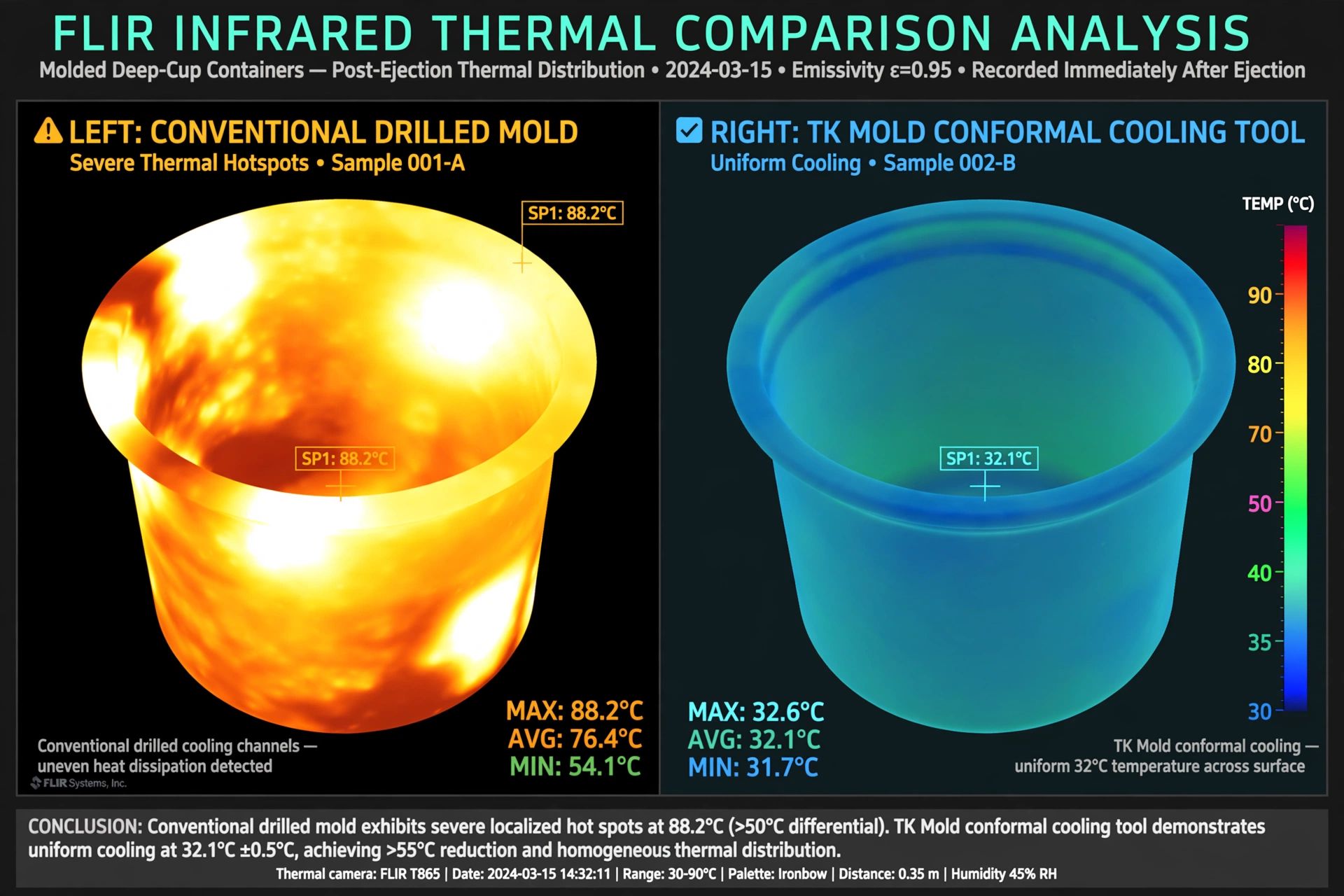
Thermal Imaging Validation
Using FLIR high-resolution thermal imaging during scientific mold trials, our engineers measure surface heat distribution immediately upon mold opening. Conformal tools demonstrate uniform color thermography, confirming that parts eject without soft, rubbery hot spots that cause post-mold sink marks. View our live scientific mold trials.
3D Metal Sintering Metallurgy: 1.2709 Maraging Steel
Conformal inserts are manufactured on industrial German EOS Direct Metal Laser Sintering (DMLS) machines using microscopic 20-micron steel powder beds. After laser fusion, inserts undergo vacuum precipitation hardening to reach 50 to 54 HRC hardness, matching the abrasive wear resistance of forged tool steels.
Post-Print Surface Finishing
While internal channels remain smooth to encourage turbulent fluid flow, all external cavity shutoff faces and cosmetic surfaces are CNC hard-milled and diamond-polished to SPI A2 standards. This hybrid manufacturing approach combines the internal geometry of additive manufacturing with the precision shutoffs of 5-axis CNC machining. Explore our DFM and Moldflow simulation capabilities.

Interactive Conformal Cooling Savings Calculator
Estimate how many seconds conformal cooling can shave off your cycle time and calculate your annual production capacity increase.
Technical Sourcing FAQ: Conformal Cooling
Want to Eliminate Cycle Delays with Conformal Cooling?
Submit your part CAD to Brandon Henderson in North Carolina. Our engineering team will run comparative thermal simulations illustrating cycle time reduction and temperature distribution.