
Engineering Guides
Welcome to the master technical engineering guide for plastic injection mold tooling. Written by journeyman toolmakers, this resource details essential rules for draft angles, wall thickness uniformity, gating selection, tool steel metallurgy, and parting line shutoffs to guarantee robust Class 101 tool performance.
Direct Engineering Summary: Fundamental Tooling Rules
Successful injection mold manufacturing depends on five core engineering rules: applying a minimum of 1.0 degree draft on smooth faces (plus 1.5 degrees per 0.025 mm of texture depth); maintaining rib thickness between 50% and 60% of the adjoining wall to eliminate sink marks; gating at the heaviest wall section toward thin features; selecting through-hardened steels (like H13 or S136 ESR at 50 to 54 HRC) for high-volume programs; and incorporating 5-degree shutoffs to prevent premature parting line wear.
1. Draft Angle Calculations & Texture Depth Rules
Draft angles are tapers applied to vertical part faces to allow the molded component to release cleanly from mold steel cores and cavities. Without adequate draft, plastic contracts tightly around male cores as it cools, resulting in excessive ejection force, surface scuffing, pin punch-through, and premature tool gouging.
- Smooth / Polished Faces (SPI A2 to B1): A baseline of 0.5 to 1.0 degree per side is recommended. For deep draws exceeding 75 mm, increase draft to 1.5 degrees minimum to minimize friction on ejector pins.
- Light Spark / EDM Textures (VDI 18 to 24): Provide a minimum of 1.5 to 2.0 degrees of draft to prevent drag marks along micro-cavity peaks.
- Heavy Grain & Mold-Tech Textures (MT-11000 series): Add 1.0 to 1.5 degrees of draft per 0.025 mm (0.001 inch) of texture depth. A texture with 0.05 mm etch depth requires at least 3.0 to 3.5 degrees of draft.
- Shutoff Bypass Angles: Steel-on-steel sliding shutoffs require a minimum of 3.0 degrees draft, with 5.0 to 7.0 degrees preferred to prevent galling.

Animated Vector: Draft Angle Clears Core Contact Instantly
2. Wall Thickness Ratios & Rib Design Rules
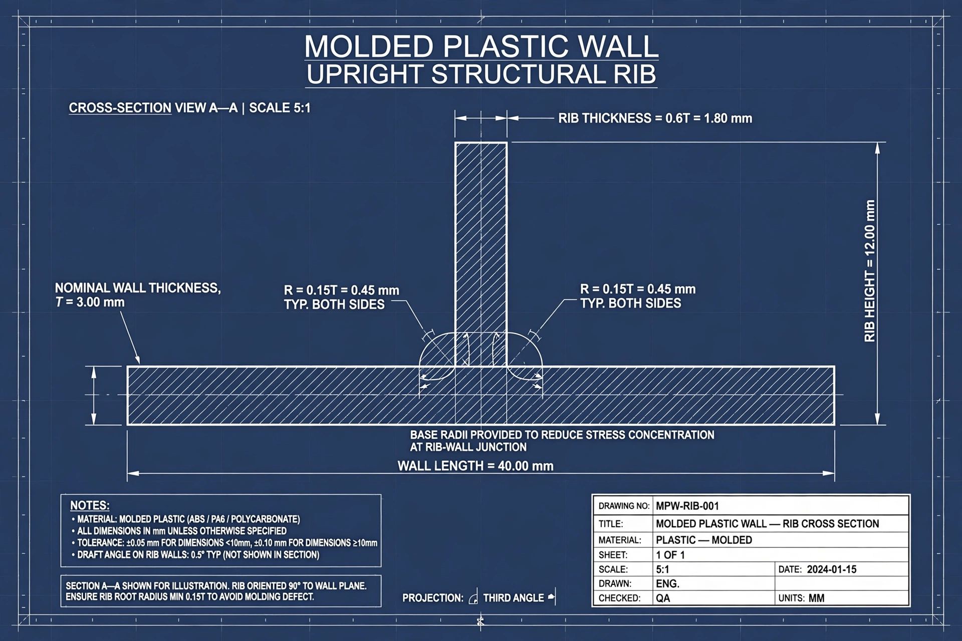
Non-uniform wall thickness is the primary driver of differential volumetric shrinkage, which induces post-mold warpage, internal voids, and surface sink marks. Maintaining constant wall sections ensures predictable resin flow and uniform cooling.
- Nominal Wall Ranges: Recommended wall thicknesses vary by polymer chemistry: Polypropylene (0.8 mm to 3.0 mm), ABS (1.2 mm to 3.5 mm), Polycarbonate (1.5 mm to 4.0 mm), Nylon 6/6 (0.8 mm to 3.0 mm).
- The 3:1 Transition Taper Rule: When wall thickness steps are unavoidable, transition gradually across a minimum 3:1 length-to-thickness chamfer or radius to prevent abrupt flow front hesitation.
- Rib-to-Wall Ratios: Internal stiffening ribs should never equal nominal wall thickness. Keep rib base thickness at 50% to 60% of the nominal wall for ABS and PC, and 40% to 50% for PP and PE.
- Coring Out Heavy Sections: Solid bosses and handles should be cored out from the non-appearance side to avoid localized thermal mass concentrations.
3. Gate Styles, Locations & Orifice Sizing
Gate selection dictates mold filling pressure, cosmetic gate vestige, packing efficiency, and weld line placement. According to materials processing data published by the National Institute of Standards and Technology (NIST), proper gate land length directly controls polymer shear heating during high-velocity injection.
| Gate Style | De-Gating Method | Vestige Profile | Ideal Application |
|---|---|---|---|
| Direct Edge Gate | Manual / Robot Trim | 0.5 to 1.5 mm tab vestige | Medium-to-large flat parts, acrylic, filled resins |
| Sub-Marine (Tunnel) | Automatic Mold Shear | Flush / slight recess | High-cavitation consumer goods, non-appearance sides |
| Cashew / Banana Gate | Automatic Mold Shear | Hidden inside geometry | Cosmetic enclosures requiring zero exterior witness marks |
| Hot Tip Valve Gate | Automatic Valve Pin | Near-zero ring vestige | Automotive fascias, medical tubes, packaging containers |
| Diaphragm Gate | Secondary Machining | Internal circular ring | Concentric tubes and cylindrical gears preventing ovality |

4. Tool Steel Selection & Hardness Guidelines
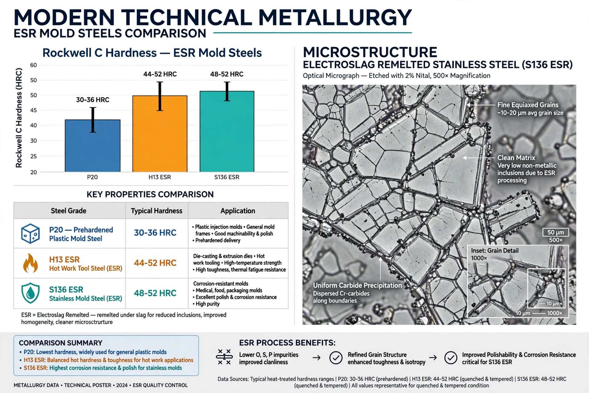
Choosing the correct mold steel requires balancing production cycle volume, resin abrasiveness, polish requirements, and thermal conductivity. Using pre-hardened steels for abrasive resins results in early parting line rounding, while using premium stainless for benign commodity resins unnecessarily inflates tooling capital costs.
| Steel Grade | Hardness | Machinability | Corrosion Resistance | Tool Life (Shots) |
|---|---|---|---|---|
| P20+Ni (1.2738) | 28 – 32 HRC | High (Pre-hardened) | Low (Requires oil coating) | 100,000 – 300,000 |
| NAK80 (P21) | 38 – 42 HRC | Excellent (Pre-hardened) | Moderate | 300,000 – 600,000 |
| H13 Premium (1.2344) | 48 – 52 HRC | Moderate (Through-hardened) | Moderate | 1,000,000+ (Class 101) |
| ASSAB S136 ESR (420) | 50 – 54 HRC | Requires Rigid Setup | Exceptional (Rust-proof) | 1,000,000+ (Mirror Polish) |
| Bohler M333 Isoplast | 54 – 58 HRC | High Rigidity Required | Maximum (Acid Proof) | 2,000,000+ (Optical Lenses) |
5. Parting Line Shutoff Angles & Kiss-Off Protection
Molded holes, snap-fit slots, and through-windows require core and cavity steel faces to meet and seal off resin flow during high clamping pressure. If shutoff faces are designed parallel to mold draw (0 degrees), the continuous scraping of steel against steel leads to galling, flash, and tool damage within a few thousand cycles.
- Bypass Shutoff Angles: Maintain a minimum 3.0 degrees of draft on bypass shutoff surfaces. A 5.0 to 7.0 degree angle is preferred for Class 101 high-speed tooling.
- Lead-In Chamfers: Incorporate 45-degree lead-in chamfers on sliding core shutoffs to ensure self-alignment prior to final platen lockup.
- Pre-Load Stand-Off Pads: Position hardened rest pads (heel blocks) outside the cavity perimeter ground 0.03 mm proud to absorb clamping shock and prevent cavity coining.
Injection Mold Design Rule Checker
Select your resin family, nominal wall thickness, and texture finish to receive instant tooling engineering recommendations:
Frequently Asked Questions: Mold Engineering Guides
Review Your Part CAD Against These Tooling Guidelines
Submit your component 3D CAD files to Brandon Henderson in North Carolina. We provide actionable DFM feedback on draft angles, wall uniformity, and gate recommendations within 24 to 48 hours.