
Understanding Custom Injection Mold Tooling Architecture
Every high-efficiency injection molding program begins with the physical tool assembly. Unlike generic modular bases or prototype hand-load inserts, custom injection mold tooling is built around the exact thermal contraction characteristics of the chosen polymer, the aesthetic demands of the part geometry, and the dynamic clamp kinematics of production injection presses.
Primary Tooling Components
A production injection mold functions as a high-pressure pressure vessel capable of containing hydraulic clamp forces exceeding one thousand tons. The assembly integrates several precision-machined subsystems:
- A-Side (Cavity Plate): The stationary half aligned with the press injection barrel, containing the cosmetic exterior geometry, runner channels, and hot sprue bushings.
- B-Side (Core Plate): The moving half attached to the ejector platen, forming internal ribs, bosses, snap locks, and structural undercuts.
- Guided Ejection System: Ejector pins, blade ejectors, stripper plates, and return pins guided by bronze-plated bushings to displace the cooled part without cosmetic deformation.
- Side-Action Cam Slides and Lifters: Mechanical slides driven by angled horn pins or hydraulic cylinders that withdraw perpendicular to the mold opening to release exterior undercuts.
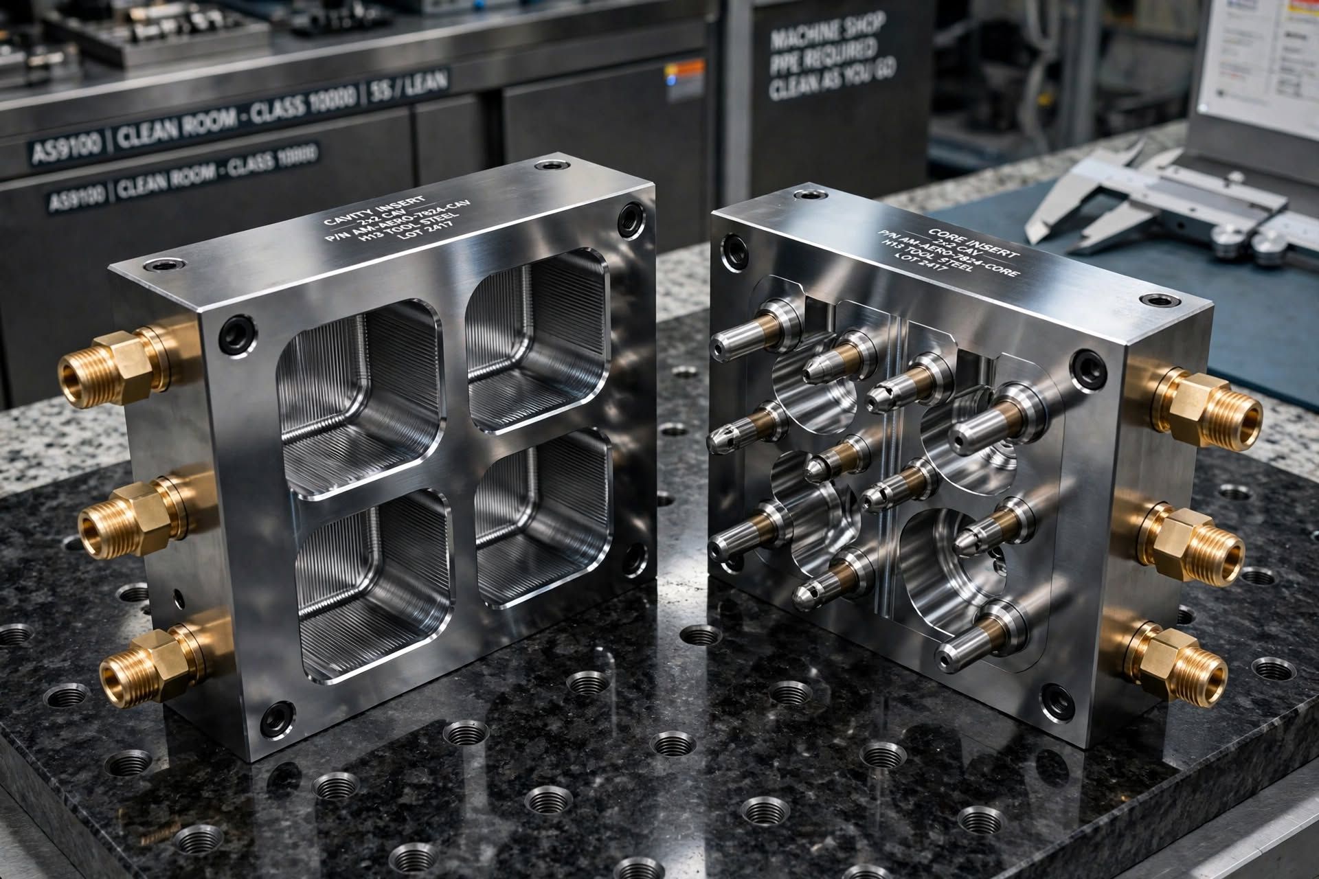
Schematic illustrating the stack-up from the top clamp plate down to the ejector housing, showing parting line seal faces, water circuit drillings, and guided pin alignment.
In high-cavitation production tools, maintaining rigidity under dynamic mechanical deflection is critical. Studies published by the National Institute of Standards and Technology on manufacturing characterization demonstrate that microscopic mechanical flexing during the packing stage directly correlates with parting line flash, uneven gate seal, and volumetric shrinkage variation across multi-cavity tools.
Plastics Industry Association (SPI) Mold Classifications
To establish clear commercial expectations between part designers and toolmakers, the Plastics Industry Association defined standard classifications spanning Class 101 down to Class 105. Tool longevity, steel grade, base hardness, and cooling circuit complexity vary significantly across each class.
| SPI Classification | Rated Lifecycle | Core and Cavity Steel | Base Hardness (HRC) | Cooling Design | Typical Applications |
|---|---|---|---|---|---|
| Class 101 | 1,000,000+ Cycles | Hardened S136 ESR, H13, 420 SS (≥48 HRC) | Pre-hardened 4140/P20 (≥28 HRC) | Internal baffled channels, conformal cooling | Medical disposables, packaging caps, automotive connectors |
| Class 102 | Up to 1,000,000 Cycles | Hardened tool steel (≥48 HRC) or NAK80 | Pre-hardened steel (≥28 HRC) | Custom drilled water lines with brass plugs | Consumer electronics enclosures, industrial housings |
| Class 103 | Up to 500,000 Cycles | P20, 718H, or pre-hardened steel (≥30 HRC) | Standard medium carbon steel | Standard through-drilled cooling circuits | Mid-volume appliances, power tool components |
| Class 104 | Up to 100,000 Cycles | Mild steel, P20, or high-tensile aluminum | Standard commercial steel | Basic cooling lines or convective cooling | Low-volume pilot runs, limited production consumer goods |
| Class 105 | Under 500 Cycles | Cast aluminum, epoxy, or soft zinc alloy | Unrated / prototype frame | None / ambient air cooling | Prototyping, functional fit checks, marketing samples |
When evaluating total cost of ownership, building an SPI Class 101 mold minimizes recurring piece-part cost. By specifying hardened stainless steel cavities and fully guided stripper plates, production operations achieve automated 24/7 continuous molding without unplanned toolroom down-time. For North American molders operating automated cells, explore our dedicated engineering support for export molds for U.S. presses built with domestic components.
Tool Steel Metallurgy and Insert Hardening
Selecting the correct tool steel formulation is the single most critical decision impacting mold life, surface optical polishability, and cycle efficiency. A mismatch between the polymer chemistry and the cavity metallurgy leads to rapid abrasive wear, pitting corrosion, or catastrophic cracking during thermal cycling.
Key Tool Steel Formulations
- ASSAB S136 ESR / 420 Stainless (50 to 54 HRC): Premium electro-slag remelted stainless steel offering maximum corrosion resistance against acidic off-gassing from PVC, POM, and flame-retardant additives. Enables diamond-paste optical finishes (SPI A1).
- Premium AISI H13 (48 to 52 HRC): Chromium-molybdenum hot-work tool steel renowned for excellent toughness and thermal fatigue resistance, documented extensively in research published by the Department of Energy Office of Scientific and Technical Information on tooling steels.
- Daido NAK80 (38 to 42 HRC): Pre-hardened precipitation-cured nickel-aluminum-copper alloy. Eliminates distortion caused by post-machining heat treatment, ideal for intricate consumer electronics ribs and deep texture etching.
- Ampco 940 Beryllium-Free Copper: High thermal conductivity copper alloy (up to four times the heat dissipation of tool steel) placed in core tips, thin blade areas, and deep boss inserts to eliminate hot spots.
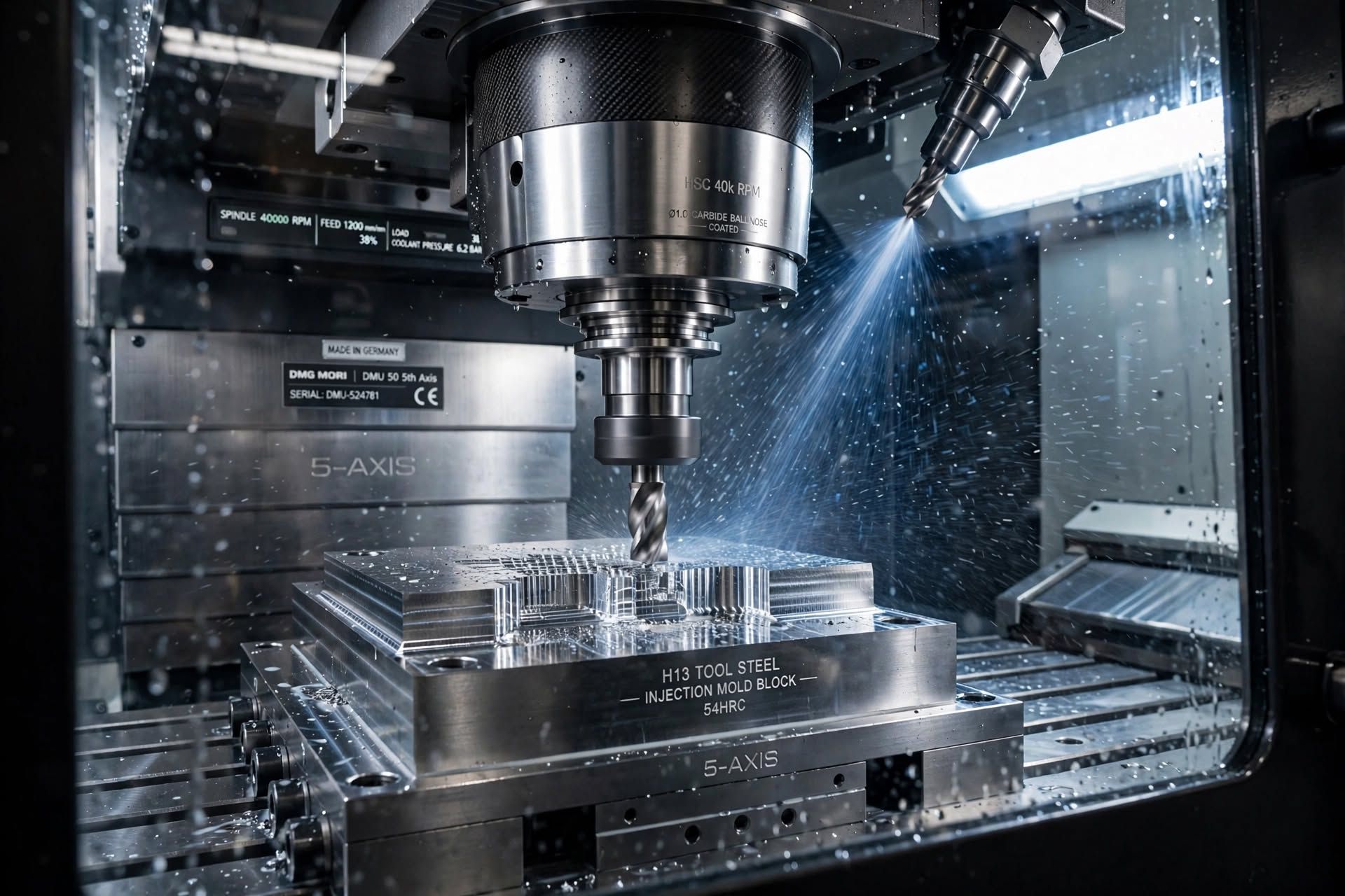
| Steel Grade | Delivery Hardness | Working Hardness | Thermal Conductivity | Polishability Rating | Wear & Corrosion Resistance |
|---|---|---|---|---|---|
| ASSAB S136 ESR | Annealed ~215 HB | 48 – 54 HRC (Vacuum Hardened) | 20 W/(m·K) | SPI A1 (Optical Mirror) | High corrosion resistance; superior abrasive wear life |
| AISI H13 Premium | Annealed ~220 HB | 48 – 52 HRC (Vacuum Hardened) | 28 W/(m·K) | SPI A2 (High Polish) | High thermal fatigue resistance; moderate corrosion |
| Daido NAK80 | Pre-hardened 38 – 42 HRC | 38 – 42 HRC (No Heat Treat) | 41 W/(m·K) | SPI A2 / A3 (Excellent) | Good machinability; low corrosion resistance |
| P20+Ni (1.2738) | Pre-hardened 28 – 32 HRC | 28 – 34 HRC (Optional Nitride) | 34 W/(m·K) | SPI B1 / B2 (Standard) | Economical; moderate wear resistance |
| Ampco 940 (CuNiCo) | Finished 28 – 32 HRC | 90 – 95 HRB (~30 HRC) | 208 W/(m·K) | SPI B1 (Functional) | Ultra-high thermal transfer; low hardness |
Gating Architecture and Mold Thermal Management
Over eighty percent of an injection molding cycle is consumed by cooling time. If heat extraction is non-uniform across the core and cavity, internal mechanical stresses trigger warpage, sink marks, and extended cycle times. Designing high-efficiency cooling circuits and balanced gating networks is essential for maximizing press output.
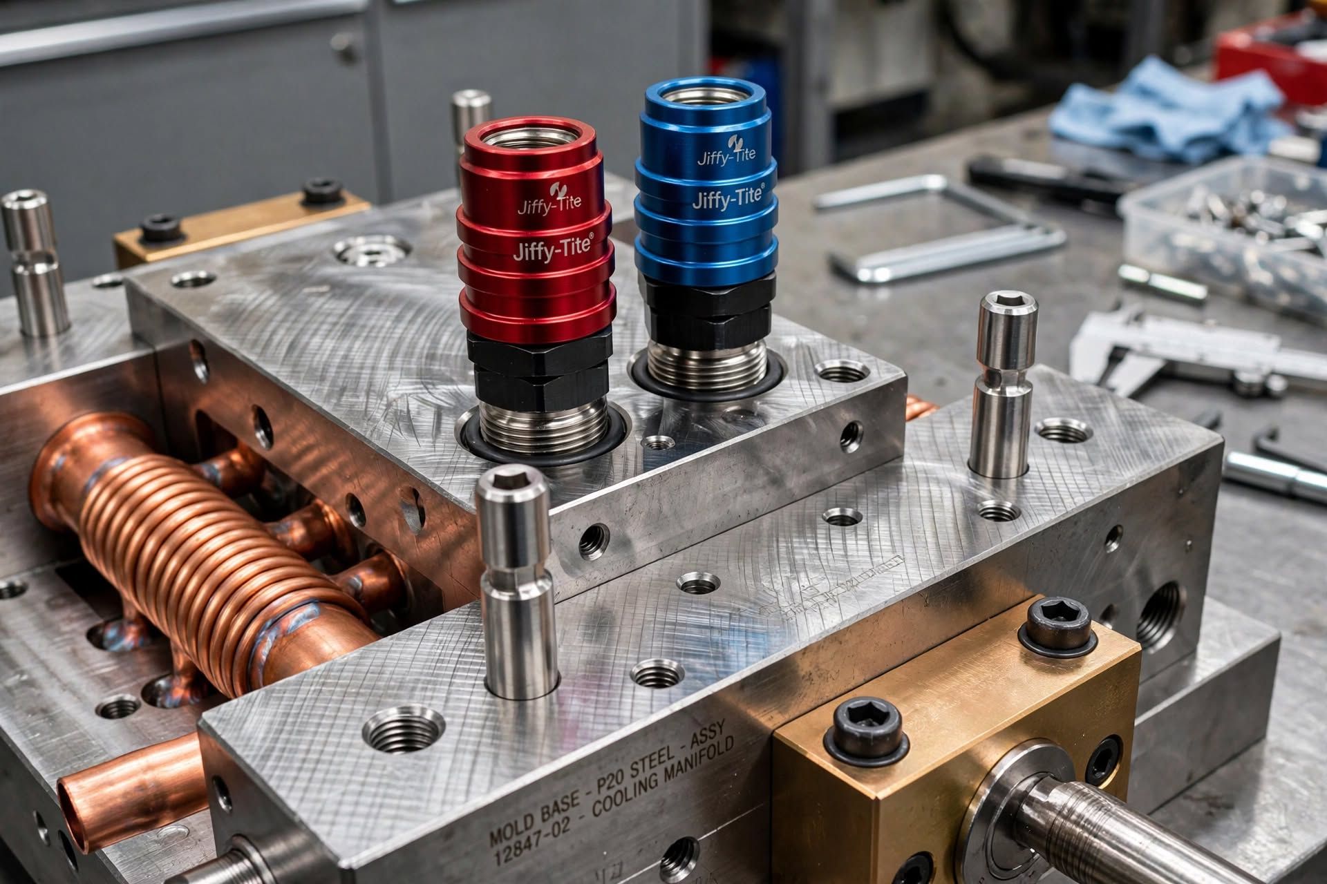
Conformal Cooling vs Conventional Drilled Circuits
Traditional straight-drilled cooling lines are limited by drill geometry, frequently leaving deep core pins and tall ribs inadequately cooled. By implementing 3D metal printed inserts with curved internal passages that mirror the product contour, temperature variations are kept within two degrees Celsius across the molding surface.
This technology reduces cycle times by up to thirty-five percent on thick-walled packaging closures and medical housings. Learn more about laser-sintered stainless steel inserts on our conformal cooling tooling page or review our high-output high-cavitation and stack mold solutions.
Step-by-Step Custom Mold Development Workflow
Transforming a raw 3D CAD design into a validated SPI Class 101 production mold follows a rigorous, phase-gated engineering methodology. Early computational review prevents costly steel modifications later in the build cycle.
1. DFM and Rheological Review
Before steel cutting commences, certified engineers run finite-element Autodesk Moldflow analyses to identify potential weld lines, air traps, and volumetric shrinkage imbalances. Read more about our in-depth DFM and Moldflow engineering services.
2. Micron CNC and Wire EDM
Blocks undergo 5-axis roughing, stress-relieving cycles, and final finishing on Makino and Sodick wire EDM centers. Shutoff surfaces are machined to sub-micron tolerances to prevent flash while facilitating gas venting along the parting line.
3. Scientific T1 Molding Validation
Initial trial out (T1) executes on specialized Japanese electric presses under decoupled scientific molding principles. We record cavity pressure sensor curves, fill time repeatability, and verify parts with comprehensive CMM dimensional inspection. Watch our recorded scientific mold trials.
Custom Tooling Specifier and Cavity Estimator
Use this interactive engineering selector to determine the ideal SPI Mold Classification, recommended cavity count, tool steel grade, and projected build lead times based on your program requirements.
Coordinate Metrology, First Article Inspection (FAI), and CMM Verification
Achieving repeatable dimensions across multi-cavity tools requires traceable metrological inspection. Every critical steel shutoff dimension and molded plastic test sample undergoes full verification inside climate-controlled quality labs maintaining NIST traceability.
Dimensional Verification Standards
Our quality control protocols comply with international dimensional metrology standards maintained by the NIST Dimensional Metrology Program. In-house inspection protocols include:
- Automated Coordinate Measuring Machines (CMM): Zeiss and Mitutoyo bridge CMMs holding volumetric accuracy to 0.0015 millimeters.
- Optical Multisensor Systems (OMM): Non-contact vision measuring for micro-fluidic geometries and thin-wall closures.
- Computed Tomography (CT) Industrial Scanning: Nondestructive 3D X-ray metrology examining internal core pin shift, void presence, and wall thickness consistency.
- Capability Studies (Cpk ≥ 1.67): Statistical process validation demonstrating process capability across 32 consecutive molding cycles.
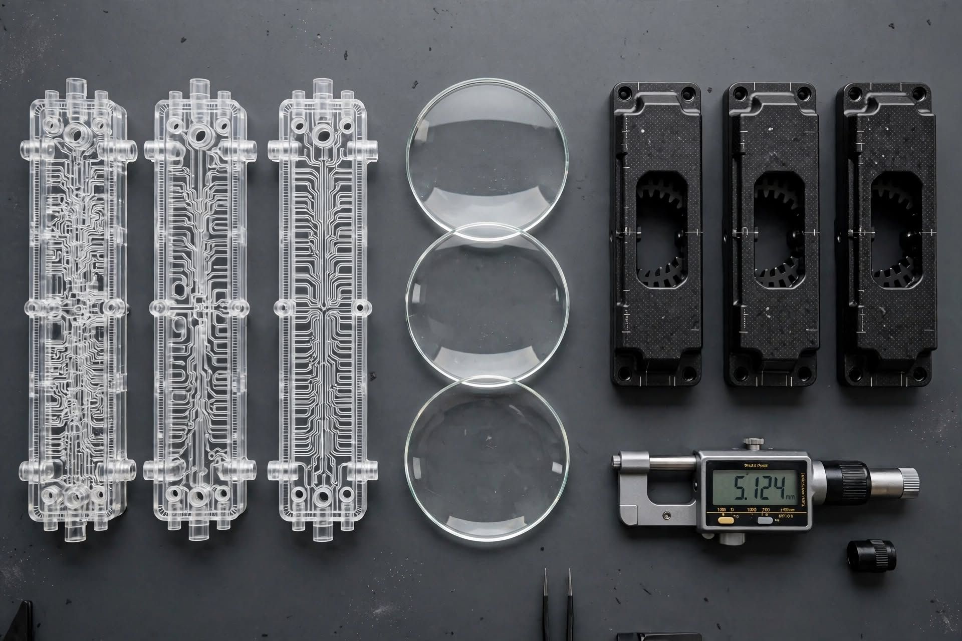
For turnkey production programs that transition directly into part molding, explore our complete contract injection molding services across cleanroom and automated production cells, or discover our specialized multi-shot injection molding capabilities for multi-color and soft-touch overmolding.
Technical Inquiries About Custom Injection Mold Tooling
Here are direct answers to common questions engineers and procurement directors evaluate when selecting an offshore or domestic tooling partner.
Ready to Review Your Part Geometry for Custom Tooling?
Connect directly with Brandon Henderson, Journeyman Tool and Die Maker (CPSP) based in North Carolina. Receive an initial Design for Manufacturability (DFM) review and comprehensive tooling quotation within twenty-four to forty-eight hours.